
Executive Summary: The Future of Volumetric Inspection in Additive Manufacturing
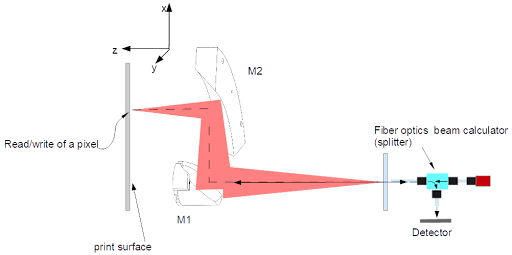
Figure 1: Integrated LFOS and SS-OCT Optical Path Synchronization
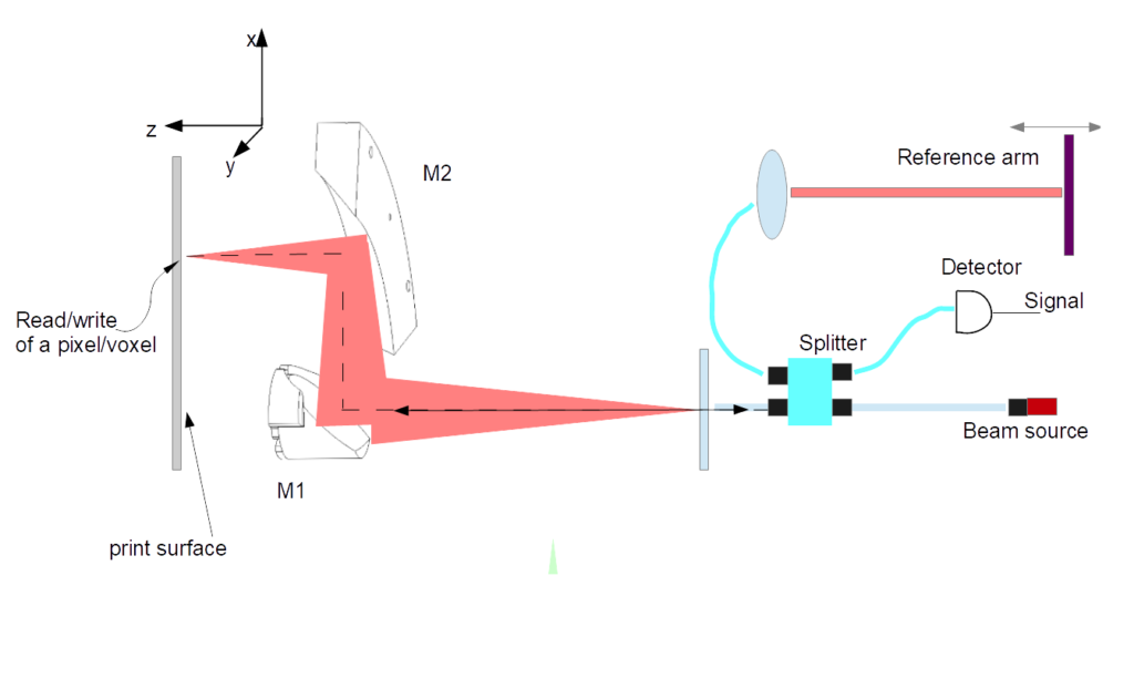
Technical Takeaway: In OCT, timing and path length are everything. The LFOS ensures that the “Sample Arm” of the interferometer remains perfectly synchronized with the “Reference Arm” at every scan coordinate.
The convergence of Lens-Free Optical Scanning (LFOS) and Optical Coherence Tomography (OCT) represents a paradigm shift in precision manufacturing and non-destructive testing. While traditional scanners are limited to surface-level “read-back” data, an LFOS-integrated OCT system enables real-time, sub-surface volumetric inspection. By eliminating the distortions inherent in lens-based optics, this multifunctional scanner provides a high-resolution, 3D internal map of a part as it is being built. This allows for the immediate detection of microscopic defects, porosity, and delamination—transforming the workflow from a “print-and-verify” process into a self-correcting, closed-loop system.
The Constraints of Traditional F-Theta Scanning Systems
Most industrial laser systems today rely on Galvanometer Scanners (GS). These systems use rotating mirrors to pivot a laser beam across a workspace. However, as the beam angles away from the center, the distance it must travel increases, causing the focal point to naturally fall in a curved arc rather than a flat plane. To correct this, manufacturers use F-Theta lenses.
While F-Theta lenses are the industry standard, they introduce three critical points of failure:
Spot Shape Distortion (The “Ellipse” Effect): As the beam reaches the edges of the lens, the laser spot stretches into an elongated ellipse. This inconsistent shape results in uneven energy distribution, which is detrimental to high-precision tasks like metal 3D printing or micro-machining.
Thermal Drift: F-Theta lenses are made of refractive materials that absorb a fraction of the laser’s energy. As the lens heats up, its refractive index changes, causing the focal point to “drift” during long operations. This leads to dimensional inaccuracies that are difficult to calibrate in real-time.
Parallax and Angle of Incidence: Because the beam is “fanned out” from a central point, it hits the target at an angle. For technologies like Optical Coherence Tomography (OCT), this angle creates shaded areas and signal noise, making it nearly impossible to get a clear, vertical “X-ray” view of the material’s internal structure at the periphery of the build plate.
The Principles of LFOS: Achieving Zero-Distortion Optical Paths
The Lens-Free Optical Scanner (LFOS) represents a fundamental redesign of laser delivery. By moving away from the “pivot-and-lens” model, LFOS employs a translational architecture that keeps the laser source and delivery optics moving in a synchronized, linear fashion. This design ensures that the laser beam is always orthogonal (perpendicular) to the target surface, regardless of its position on the build plate.
The advantages of this lens-free approach are three-fold:
Constant Focal Point and Spot Size: Since the distance from the optics to the target never changes, the laser spot remains a perfect circle with consistent energy density from the center to the very edge of the workspace. This eliminates the “ellipse effect” that plagues galvanometer systems.
Thermal Stability: By removing the refractive F-Theta lens, the system eliminates the primary source of thermal drift. Without a lens to heat up and shift the focus, the LFOS maintains sub-micron precision over long operating hours, ensuring absolute dimensional stability.
The Ideal Platform for Volumetric Data: Because the beam is always vertical, there is no parallax error. This is the critical “enabling factor” for Optical Coherence Tomography (OCT). The reflected light returns to the sensor on a straight, predictable path, providing the clean signal necessary for high-fidelity 3D internal imaging.
What is Optical Coherence Tomography (OCT)? High-Resolution “X-Ray Vision” for Industry
Often described as “optical ultrasound,” Optical Coherence Tomography (OCT) is a non-contact, non-invasive imaging technique that provides micrometer-resolution, 3D views of the internal structures of materials. While it is widely known in ophthalmology for mapping the human retina, OCT has transitioned into a critical tool for industrial Non-Destructive Testing (NDT) and advanced manufacturing.
Unlike traditional cameras that only capture surface data, OCT utilizes low-coherence interferometry. The system splits a light beam into two paths: a “sampling beam” that strikes the object and a “reference beam” that reflects off a mirror. When the sampling beam penetrates the material and bounces off internal layers or defects, it recombines with the reference beam. By measuring the resulting interference pattern, the system can calculate the “time-of-flight” of the light with extreme precision.
This process allows for the creation of:
A-Scans: Single-point depth profiles showing material density.
B-Scans: Cross-sectional “slices” that reveal internal voids, cracks, or layer boundaries.
3D Volumetric Maps: A complete, transparent reconstruction of the object’s internal and external geometry.
The Synergy: Why LFOS is the Ideal Platform for OCT
While many have attempted to integrate Optical Coherence Tomography (OCT) into traditional galvanometer-based systems, the results are often compromised by the optics themselves. Because an OCT sensor relies on the precise “time-of-flight” of reflected light, the hardware delivering the beam must be geometrically perfect.
This is where the synergy of the Lens-Free Optical Scanner (LFOS) becomes essential. The LFOS architecture solves the two primary data-integrity issues found in traditional OCT integration:
Zero Angle of Incidence (Orthogonality): In a traditional scanner, the beam hits the surface at an angle that increases as it moves away from the center. This creates “shadowing” inside the material, where the OCT cannot “see” behind internal features. Because LFOS maintains a constant vertical beam, it provides a true, top-down volumetric scan with zero parallax error across the entire build area.
Elimination of “Speckle” and Signal Noise: F-Theta lenses introduce internal reflections and chromatic aberrations that can pollute the sensitive interferometry data of an OCT system. By removing the lens entirely, LFOS provides a clear, unobstructed optical path. This results in a significantly higher signal-to-noise ratio, allowing for the detection of defects that are 5–10x smaller than those detectable by lens-based hybrids.
By marrying these two technologies, Tecnica has moved beyond simple 3D printing into the realm of Active Metrology, where the scanner is not just a tool for creation, but a high-speed, 3D laboratory for real-time verification.
Beyond Manufacturing: Cross-Industry Applications for LFOS-OCT
The combination of a lens-free, orthogonal scan path and high-resolution depth imaging creates a versatile tool for Non-Destructive Testing (NDT). Because the LFOS can scale to different workspace sizes without losing focus, it is being adopted by industries where internal integrity is a matter of safety and regulatory compliance:
Aerospace and Defense: Inspecting composite materials and turbine blades for micro-delamination or internal fatigue cracks. The LFOS-OCT system can scan large surfaces while maintaining the sub-micron resolution needed to find defects that X-ray systems might miss.
Pharmaceuticals and Biotech: Real-time monitoring of tablet coating thickness and uniformity. Ensuring the precise depth of a sustained-release coating is critical for dosage accuracy, and OCT provides a non-contact way to verify this during the production flow.
Semiconductor and Electronics: Verifying the integrity of micro-solder bumps and multi-layer circuit packaging. As components shrink, the “top-down” orthogonal view of the LFOS is the only way to inspect deep into high-density architectures without parallax distortion.
Art Conservation and Forensic Science: Analyzing the hidden layers of historical artifacts or paintings. The non-invasive nature of OCT allows historians to see underdrawings or structural repairs beneath surface pigments without touching or damaging the original work.
- A-Scan: A 1D depth profile.
- B-Scan: A 2D cross sectional slice.
- Volumetric Inspection: The 3D mapping of both internal and external
- Orthogonality (0° Incidence): A beam path perfectly perpendicular to the surface, eliminating shadows and distortion.
- Interferometry: The physics of combining light waves to measure sub-micron distances and material depth.
- LFOS: Lens-Free Optical Scanner.
- Thermal Drift: Accuracy loss caused by lenses heating up and shifting the laser’s focal point during operation.
- SS-OCT: Swept Source OCT; the fastest form of internal imaging using a tunable laser for real-time data.
- Signal-to-Noise Ratio (SNR): The clarity of the data; higher SNR allows for the detection of smaller internal defects.
The Constraints of Traditional F-Theta Scanning Systems
Most industrial laser systems today rely on Galvanometer Scanners (GS). These systems use rotating mirrors to pivot a laser beam across a workspace. However, as the beam angles away from the center, the distance it must travel increases, causing the focal point to naturally fall in a curved arc rather than a flat plane. To correct this, manufacturers use F-Theta lenses.
While F-Theta lenses are the industry standard, they introduce three critical points of failure:
Spot Shape Distortion (The “Ellipse” Effect): As the beam reaches the edges of the lens, the laser spot stretches into an elongated ellipse. This inconsistent shape results in uneven energy distribution, which is detrimental to high-precision tasks like metal 3D printing or micro-machining.
Thermal Drift: F-Theta lenses are made of refractive materials that absorb a fraction of the laser’s energy. As the lens heats up, its refractive index changes, causing the focal point to “drift” during long operations. This leads to dimensional inaccuracies that are difficult to calibrate in real-time.
Parallax and Angle of Incidence: Because the beam is “fanned out” from a central point, it hits the target at an angle. For technologies like Optical Coherence Tomography (OCT), this angle creates shaded areas and signal noise, making it nearly impossible to get a clear, vertical “X-ray” view of the material’s internal structure at the periphery of the build plate.
The Principles of LFOS: Achieving Zero-Distortion Optical Paths
The Lens-Free Optical Scanner (LFOS) represents a fundamental redesign of laser delivery. By moving away from the “pivot-and-lens” model, LFOS employs a translational architecture that keeps the laser source and delivery optics moving in a synchronized, linear fashion. This design ensures that the laser beam is always orthogonal (perpendicular) to the target surface, regardless of its position on the build plate.
The advantages of this lens-free approach are three-fold:
Constant Focal Point and Spot Size: Since the distance from the optics to the target never changes, the laser spot remains a perfect circle with consistent energy density from the center to the very edge of the workspace. This eliminates the “ellipse effect” that plagues galvanometer systems.
Thermal Stability: By removing the refractive F-Theta lens, the system eliminates the primary source of thermal drift. Without a lens to heat up and shift the focus, the LFOS maintains sub-micron precision over long operating hours, ensuring absolute dimensional stability.
The Ideal Platform for Volumetric Data: Because the beam is always vertical, there is no parallax error. This is the critical “enabling factor” for Optical Coherence Tomography (OCT). The reflected light returns to the sensor on a straight, predictable path, providing the clean signal necessary for high-fidelity 3D internal imaging.
What is Optical Coherence Tomography (OCT)? High-Resolution “X-Ray Vision” for Industry
Often described as “optical ultrasound,” Optical Coherence Tomography (OCT) is a non-contact, non-invasive imaging technique that provides micrometer-resolution, 3D views of the internal structures of materials. While it is widely known in ophthalmology for mapping the human retina, OCT has transitioned into a critical tool for industrial Non-Destructive Testing (NDT) and advanced manufacturing.
Unlike traditional cameras that only capture surface data, OCT utilizes low-coherence interferometry. The system splits a light beam into two paths: a “sampling beam” that strikes the object and a “reference beam” that reflects off a mirror. When the sampling beam penetrates the material and bounces off internal layers or defects, it recombines with the reference beam. By measuring the resulting interference pattern, the system can calculate the “time-of-flight” of the light with extreme precision.
This process allows for the creation of:
A-Scans: Single-point depth profiles showing material density.
B-Scans: Cross-sectional “slices” that reveal internal voids, cracks, or layer boundaries.
3D Volumetric Maps: A complete, transparent reconstruction of the object’s internal and external geometry.
The Synergy: Why LFOS is the Ideal Platform for OCT
While many have attempted to integrate Optical Coherence Tomography (OCT) into traditional galvanometer-based systems, the results are often compromised by the optics themselves. Because an OCT sensor relies on the precise “time-of-flight” of reflected light, the hardware delivering the beam must be geometrically perfect.
This is where the synergy of the Lens-Free Optical Scanner (LFOS) becomes essential. The LFOS architecture solves the two primary data-integrity issues found in traditional OCT integration:
Zero Angle of Incidence (Orthogonality): In a traditional scanner, the beam hits the surface at an angle that increases as it moves away from the center. This creates “shadowing” inside the material, where the OCT cannot “see” behind internal features. Because LFOS maintains a constant vertical beam, it provides a true, top-down volumetric scan with zero parallax error across the entire build area.
Elimination of “Speckle” and Signal Noise: F-Theta lenses introduce internal reflections and chromatic aberrations that can pollute the sensitive interferometry data of an OCT system. By removing the lens entirely, LFOS provides a clear, unobstructed optical path. This results in a significantly higher signal-to-noise ratio, allowing for the detection of defects that are 5–10x smaller than those detectable by lens-based hybrids.
By marrying these two technologies, Tecnica has moved beyond simple 3D printing into the realm of Active Metrology, where the scanner is not just a tool for creation, but a high-speed, 3D laboratory for real-time verification.
Beyond Manufacturing: Cross-Industry Applications for LFOS-OCT
The combination of a lens-free, orthogonal scan path and high-resolution depth imaging creates a versatile tool for Non-Destructive Testing (NDT). Because the LFOS can scale to different workspace sizes without losing focus, it is being adopted by industries where internal integrity is a matter of safety and regulatory compliance:
Aerospace and Defense: Inspecting composite materials and turbine blades for micro-delamination or internal fatigue cracks. The LFOS-OCT system can scan large surfaces while maintaining the sub-micron resolution needed to find defects that X-ray systems might miss.
Pharmaceuticals and Biotech: Real-time monitoring of tablet coating thickness and uniformity. Ensuring the precise depth of a sustained-release coating is critical for dosage accuracy, and OCT provides a non-contact way to verify this during the production flow.
Semiconductor and Electronics: Verifying the integrity of micro-solder bumps and multi-layer circuit packaging. As components shrink, the “top-down” orthogonal view of the LFOS is the only way to inspect deep into high-density architectures without parallax distortion.
Art Conservation and Forensic Science: Analyzing the hidden layers of historical artifacts or paintings. The non-invasive nature of OCT allows historians to see underdrawings or structural repairs beneath surface pigments without touching or damaging the original work.
Technical Appendix: System Architecture & Visual Reference
This section details the mechanical and optical configurations of the LFOS-OCT platform. By referencing the figures below, technical users can understand the precise path of the laser and the unique scanning dynamics of the system.
I. The Optical Engine: Focal Control
The LFOS achieves its “Lens-Free” status through a specialized reflective geometry.
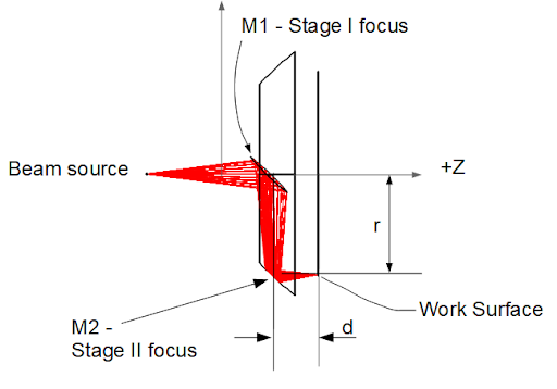
Figure 2: LFOS Beam Focus Mechanism This schematic illustrates the dual-mirror structure. Unlike a refractive lens that bends light, the LFOS uses a precise two-mirror configuration to direct and focus the beam. This path ensures that the focal point remains locked to the work surface without the chromatic aberration or thermal drift associated with glass optics.
II. Operational Visualization
The translational nature of the LFOS allows for a stable, repeatable “writing” and “reading” process.
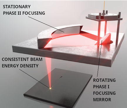
Figure 3: 3D Rendering of LFOS Operation This rendering demonstrates the LFOS in a standard printing/scanning configuration. It highlights the linear motion of the scanning head, showing how the entire optical assembly moves to maintain a constant distance from the build plate.
III. OCT Integration: Mirror vs. Fiber Architectures
Tecnica’s architecture is adaptable, allowing for different methods of splitting the light beam for interferometry.
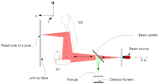
Figure 4: LFOS-OCT with Mirror Beam Splitter This 3D rendering shows the integration of OCT using a free-space mirror beam splitter. This setup is ideal for high-power applications where minimal signal loss is required during the “writing” phase while maintaining a clear return path for the “reading” phase.
Figure 5: LFOS-OCT with Fiber Beam Splitter In this configuration, a fiber-optic splitter is utilized. This allows for a more compact and flexible optical delivery, often preferred in environments where the laser source needs to be decoupled from the moving scanning head for better vibration control or thermal management.
IV. Scanning Dynamics
The way the beam moves across the surface is fundamental to the speed and coverage of the system.
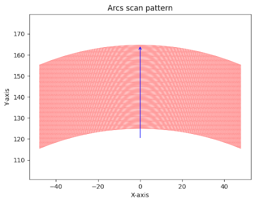
Figure 6: Arcs Scan Pattern This diagram illustrates the Arc-based scanning movement. Because the LFOS uses a translational arm, the beam traces precise arcs across the workspace. This pattern is mathematically optimized to ensure total coverage of the build area while maintaining the orthogonal (perpendicular) orientation necessary for accurate OCT depth data.
Figures:
Technical Appendix: Advanced OCT Modalities & Signal Processing
To achieve high-speed volumetric imaging, the LFOS platform is designed to be compatible with advanced OCT signal processing techniques. Understanding the evolution from Time Domain to Swept Source imaging is key to appreciating the speed and sensitivity of the Tecnica system.
Comparing OCT Modalities
| Feature | Time Domain (TD-OCT) | Spectral Domain (SD-OCT) | Swept Source (SS-OCT) |
| Reference Arm | Moving (Mechanical) | Fixed (Static) | Fixed (Static) |
| Data Acquisition | Sequential (One point at a time) | Simultaneous (Full depth via Spectrometer) | Rapid Frequency Sweep (Tunable Laser) |
| Speed | Slow | Fast | Ultra-Fast |
| Best For | Legacy Systems | General Material Inspection | High-Speed Industrial/LFOS |
Optical Coherence Tomography (OCT) is an imaging technique that leverages the coherence properties of light to capture high-resolution, cross-sectional images of biological tissues. The fundamental working principle of OCT is based on low-coherence interferometry, which involves splitting a light beam into two paths: one directed towards the sample and the other towards a reference mirror.
When light reflects back from different layers within the sample and combines with the light from the reference path, interference patterns are produced. These patterns contain information about the distance and reflectivity of the sample’s internal structures. The degree of interference depends on the coherence length of the light source, which determines how well the light waves overlap. By analyzing these interference signals, OCT systems can generate detailed images of the sample’s internal microstructure.
Why Swept Source OCT (SS-OCT) is the Standard for LFOS
While traditional Time Domain OCT relies on a moving reference mirror (which is too slow for industrial speeds), modern high-performance systems utilize Spectral Domain or Swept Source architectures.
Swept Source OCT (SS-OCT) is particularly synergistic with the LFOS for several reasons:
Frequency-Swept Tunable Lasers: SS-OCT utilizes a laser that rapidly sweeps across a range of wavelengths. As shown in our architecture diagrams, this allows the system to capture a full depth profile (A-scan) for every single wavelength sweep.
Extended Imaging Depth: SS-OCT provides a longer imaging range than SD-OCT, which is vital when inspecting complex 3D-printed geometries or deep internal structures in aerospace components.
Superior Signal-to-Noise Ratio: The use of narrow linewidth tunable lasers enhances sensitivity. When combined with the orthogonal beam path of the LFOS, the resulting data is remarkably clean, allowing for the detection of defects that would be lost in the noise of a lens-based system.
Conclusion: Towards a Self-Correcting, Closed-Loop Future
Conclusion: Towards a Self-Correcting, Closed-Loop Future
The integration of Lens-Free Optical Scanning (LFOS) and Optical Coherence Tomography (OCT) marks the end of the “trial-and-error” era in advanced manufacturing and inspection. By combining a distortion-free optical path with the ability to see beneath the surface in real-time, Tecnica is enabling a closed-loop manufacturing environment.
In this new paradigm, the system does not simply follow a set of instructions; it observes its own work. Whether it is detecting a microscopic void in a 3D-printed aerospace part or verifying the uniformity of a pharmaceutical coating, the LFOS-OCT platform provides the data necessary for autonomous quality correction. As industries move toward Industry 4.0 standards, the ability to perform high-speed, volumetric inspection at the point of production will be the deciding factor in reducing waste, ensuring safety, and achieving unprecedented levels of precision.
References:
[1] Bibas, C. Lens-Free Optical Scanners for Metal Additive Manufacturing. JOM 74, 1176–1187 (2022). https://doi.org/10.1007/s11837-021-05044-8
[2] Huang, D., Swanson, E. A., Lin, C. P., Schuman, J. S., Stinson, W. G., Chang, W., … & Fujimoto, J. G. (1991). Optical Coherence Tomography. Science, 254(5035), 1178-1181.
[3] Fercher, A. F., Hitzenberger, C. K., Kamp, G., & El-Zaiat, S. Y. (1995). Measurement of intraocular distances by backscattering spectral interferometry. Optics Communications, 117(1-2), 43-48.
[4] Drexler, W., & Fujimoto, J. G. (Eds.). (2008). Optical Coherence Tomography: Technology and Applications. Springer Science & Business Media.
[5] Choma, M. A., Sarunic, M. V., Yang, C., & Izatt, J. A. (2003). Sensitivity advantage of swept source and Fourier domain optical coherence tomography. Optics Express, 11(18), 2183-2189.
[6] Bouma, B. E., & Tearney, G. J. (Eds.). (2002). Handbook of Optical Coherence Tomography. Marcel Dekker, Inc.
[7] Leitgeb, R. A., Hitzenberger, C. K., & Fercher, A. F. (2003). Performance of fourier domain vs. time domain optical coherence tomography. Optics Express, 11(8), 889-894.
[8] Wojtkowski, M., Srinivasan, V. J., Ko, T. H., Fujimoto, J. G., Kowalczyk, A., & Duker, J. S. (2004). Ultrahigh-resolution, high-speed, Fourier domain optical coherence tomography and methods for dispersion compensation. Optics Express, 12(11), 2404-2422.
Back to Standards in AM home page


